


 6 / 104

4
THE CAMLOG
®
IMPLANT SYSTEM
SYSTEM INFORMATION
CAMLOG
®
IMPLANTATSYSTEM
CAMLOG
®
IMPLANTATLINIEN
CAMLOG
®
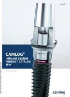
SCREW-LINE Implants
SCREW-LINE implants represent conical self-tapping screw
implants in their geometry and are available with Promote
®
(1.4 mm machined implant neck part) and Promote
®
plus
(0.4 mm machined implant neck part) surfaces.
Both implant versions include the Tube-in-Tube™ Inner con-
figuration with square grooves making the Platform Switch-
ing option available to the user.
CAMLOG
®
SCREW-LINE Implants are mounted in the sterile
packaging with an insertion post color-coded based on the
diameter. Implant diameters: 3.3/3.8/4.3/5.0/6.0 mm. Implant
lengths: 9/11/13/16 mm.
CAMLOG
®
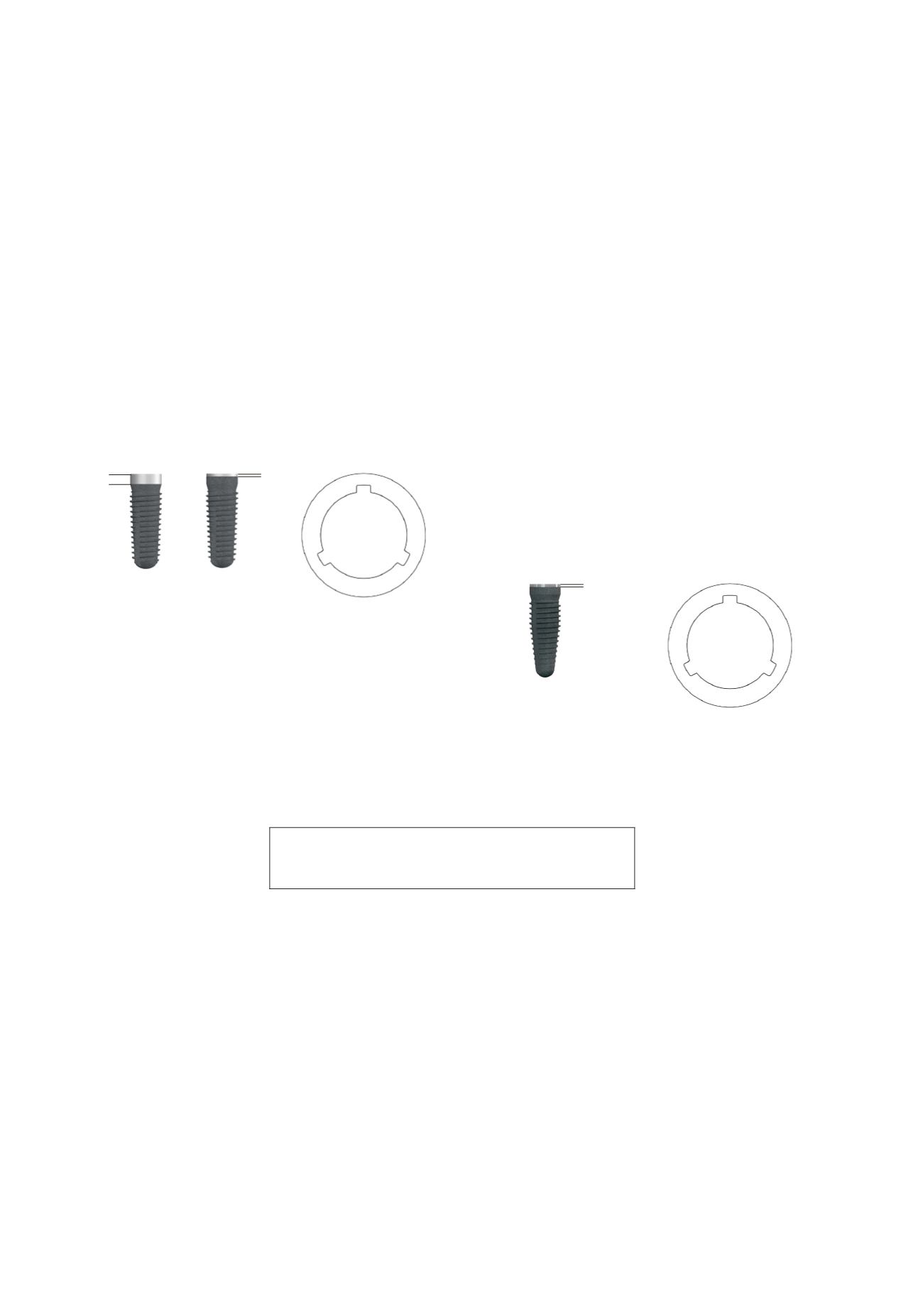
ROOT-LINE 2 Implants
CAMLOG
®
ROOT-LINE 2 Implants represent root-shaped
screw implants in terms of their outer geometry. The geometry
of the implant body allows its use at limited apical bone and
is easy to insert due to self-centering.
The outer surface of the implants is abrasive-blasted and
acid-etched (Promote
®
surface structure). The implants are
available with Promote
®
plus surface (0.4 mm machined
implant neck area). The implant shoulder is machined.
The implants are equipped with the proven Tube-in-Tube™
implant-abutment connection and feature three symmetrically
arranged angular grooves in the cylindrical part of the implant
neck. The implants can therefore be used for the Platform
Switching option.
CAMLOG
®
ROOT-LINE 2 Implants are mounted in the sterile
packaging with an insertion post color-coded based on the
diameter.
Implant diameters: 3.3/3.8/4.3/5.0/6.0 mm.
Implant lengths: 9/11/13/16 mm.
Promote
®
plus
Promote
®
1.4 mm
0.4 mm
Note: The option of Platform Switching may only
be used with CAMLOG
®
SCREW-LINE Implants with
K article numbers!
Promote
®
plus
0.4 mm