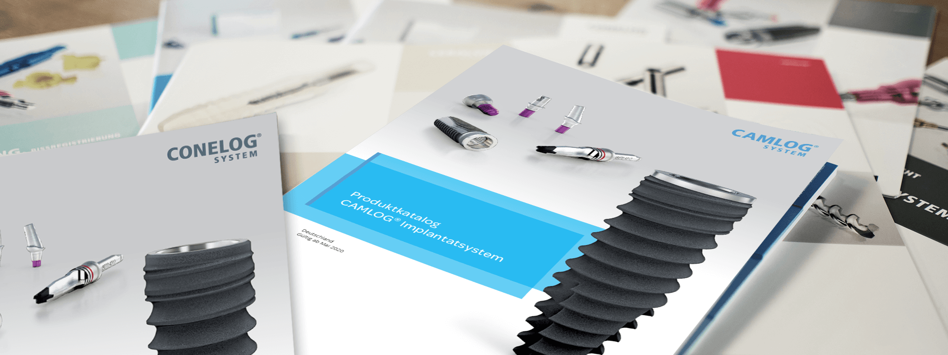
CAMLOG ROOT-LINE 2 Surgical Procedure
18 CAMLOG ® ROOT-LINE 2 IMPLANT FINAL PROSTHESIS DESIGN The surgical feasibility of the treatment sequence is checked with reference to the clinical situation, the casts, the x-ray findings and the computer-sup- ported planning. Depending on the clinical situation, periodontal or aug- mentation interventions are performed before implant surgery or at the time of the implant placement. INDIVIDUALIZATION OF THE PROSTHETIC DESIGN The patient’s wishes regarding the scope and costs of the implant-sup- ported prosthetic restoration expressed in the patient interview are incor- porated into the individual prosthesis design. The number of implants, the requirement for augmentation measures and/or required soft-tissue correc- tions are determined exclusively by local conditions and the prosthetic design. This interview must be documented in detail and the patient must sign a statement of consent before implementing the treatment process. PLANNING THE TREATMENT SEQUENCE Now that the prosthetic goal has been defined, the required treatment steps are specified in a backward planning process. This process must consider the required healing time, particularly in connection with augmen- tation measures. DOCUMENTION OF PATIENT INTERVIEW/PATIENT EXPLANATION The results of the planning process are discussed with the patient. Casts, x-ray images and the planning devices (wax-up/set-up) as well as the pre- sentation of the completed computer-supported planning are helpful here. The following criteria are considered: • Initial situation • Wishes and expectations regarding esthetics, function and comfort • Effort/benefit ratio • Costs • Risk • Duration of treatment • Restrictions on comfort during treatment. FABRICATING THE DRILLING TEMPLATE WITH CT-TUBES FOR CT PLANNING If a planning or x-ray template with tubes for CT planning was created, it can be converted into a drilling template after adjusting the tube positions based on the implant planning. If required, the template is reduced to an outline after preparation of the flap to ensure it stays in position during sur- gery (dental or gingival base outside the surgical area). PILOT DRILLING WITH CT-TUBE FOR CT PLANNING The pilot drill without coil with of 2.0 mm diameter is also available for use with the CT-tube for CT-planning with 2.1 mm internal diameter. There are ring markings the lower edges of which show drilling depths for 7, 9, 11, 13, 16, 18 and 20 mm each in the working area of the drill. The width of the ring markings is 0.4 mm. The 18 and 20 mm markings are not filled in and are used for orientation when using the 4 mm long CT-tube with 2.1 mm inter- nal diameter. IMPORTANT NOTE Only use CT-tubes for CT-planning with 2.1 mm internal diameter in conjunction with the pilot drill! 11 mm 13 mm 16 mm 18 mm 20 mm Pilot drill, without coil, Ø 2.0 mm CT-tube for CT planning, inner Ø 2.1 mm 9 mm 7 mm IMPLANT POSITION PLANNING
RkJQdWJsaXNoZXIy MTE0MzMw